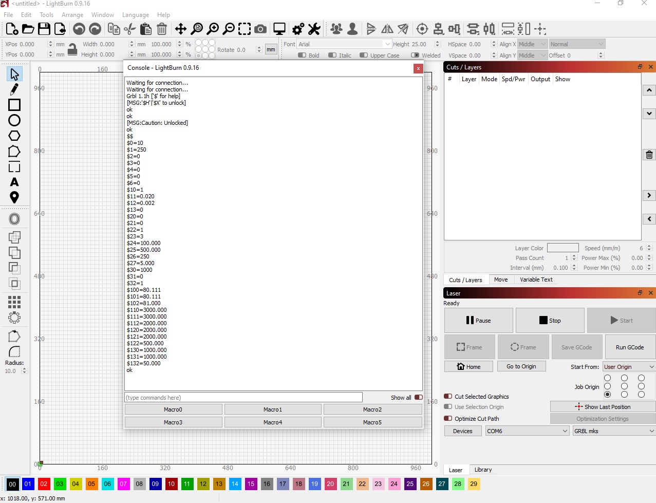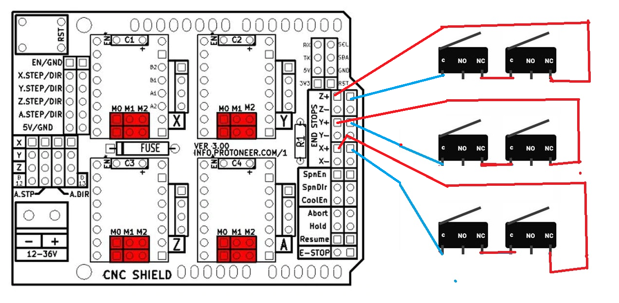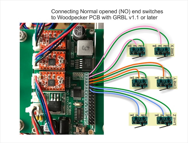
$27=1.0 (homing pull-off, mm) – amount of pullback when homing routine hits a switch.$26=50 (homing debounce, msec) – debounce time in milliseconds for homing switches.$25=1000.000 (homing seek, mm/min) – speed of movement for first part of homing cycle.$24=200.000 (homing feed, mm/min) – speed of movement for last part of homing cycle.Last 3 bits set direction for ZYX respectively invert mask: 00000011) – sets direction of travel for homing cycle for each axis. $22=1 (homing cycle, bool) – enable/disable homing cycle.$21=0 (hard limits, bool) – enable/disable hard limits (switches).


$2=1 (step port invert mask: 00000000) – These are binary mask bits that set the polarity of the step pulse.Setting this to 255 keeps motors always enabled. $1=255(step idle delay, msec) – This is the delay in milliseconds after a move instruction before the stepper motors are disabled.$0=10 (step pulse, usec) – This is the width of the step pulse in microseconds sent to the stepper drive.Each is followed by a quick reference of what it does. We’ll start out with a list of the settings used by GRBL, note that these are settings for a Big Ox type machine with belt drive and 4 axis motors. These internal settings consist of things like customizing the steps/mm of the stepper motor/driver/axis type and setting up the directions and enabling optional features. GRBL has a list of internal variables which must be customized for the machinery connected to the controller. Now that we have GRBL up and running, it’s time to get the settings for GRBL lined up with our machine.


 0 kommentar(er)
